Table of Contents
- I. Introduction and Conceptual Models for 12 March 1996/06.00 UTC
- II. Conceptual Models - Forecast for 12 March 1996/12.00 UTC and 18.00 UTC
- III. "Special Investigation": Discrimination between and separation of "Wave" and "Front Intensification by Jet Crossing"
Introduction and short case description
|
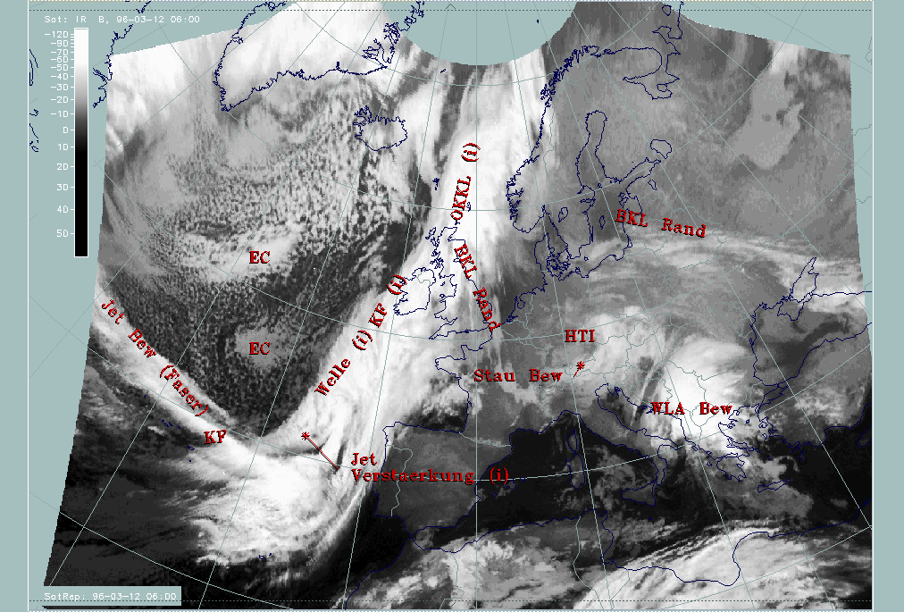
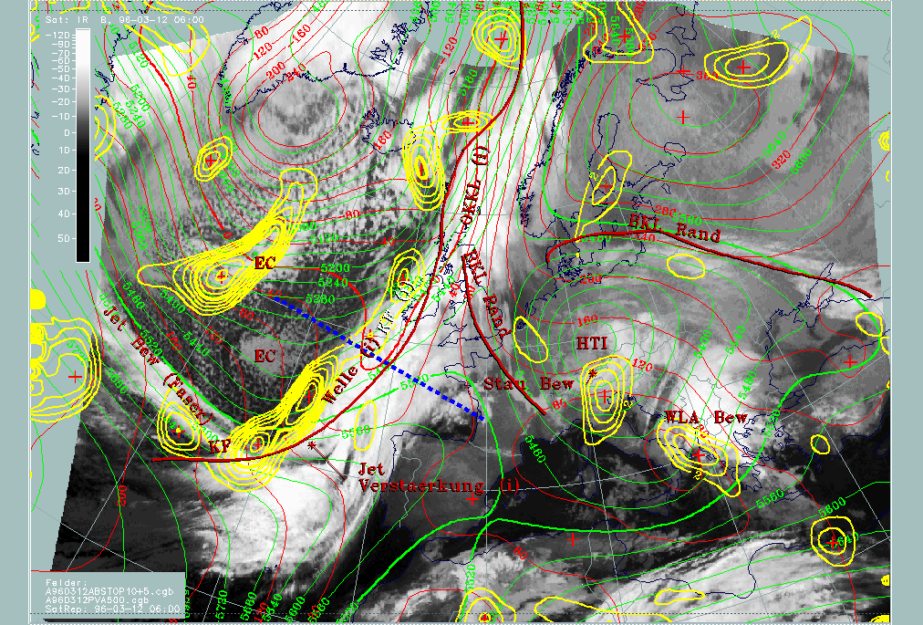
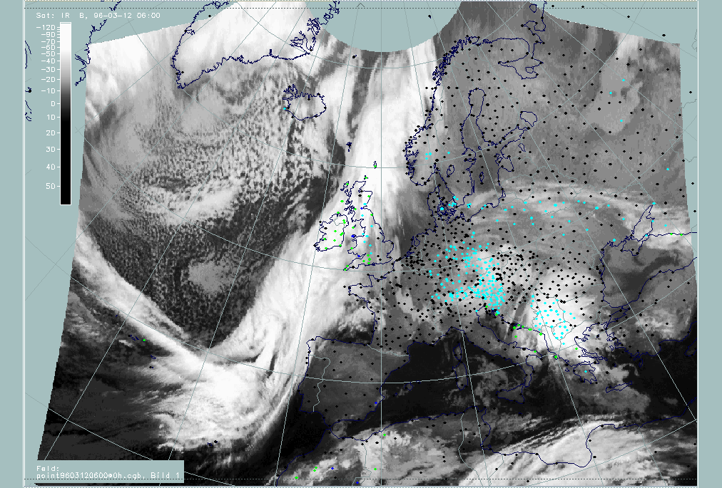
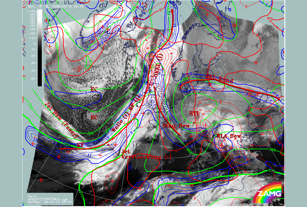
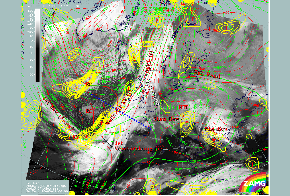
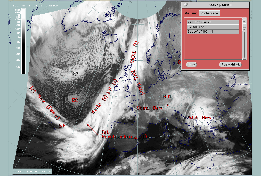
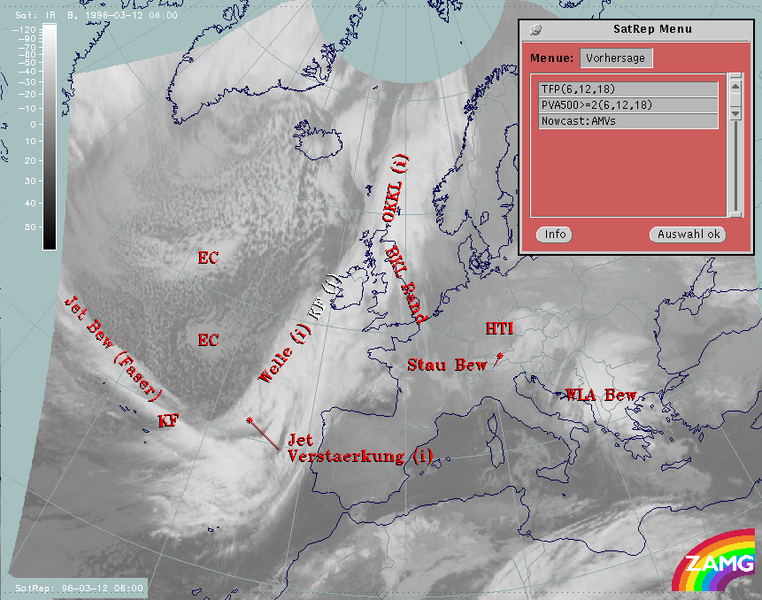
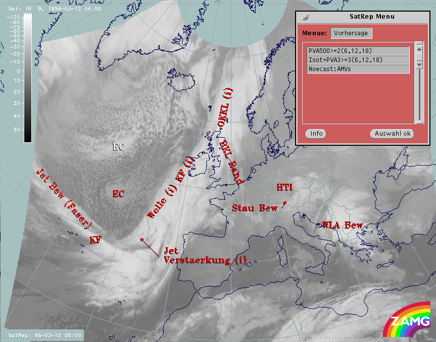
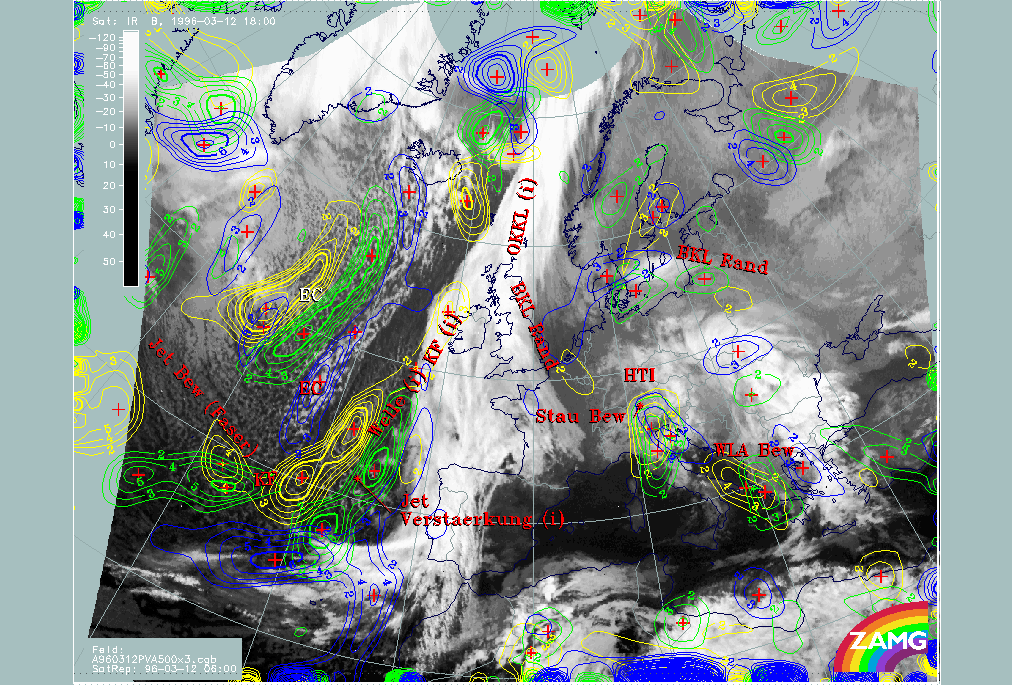
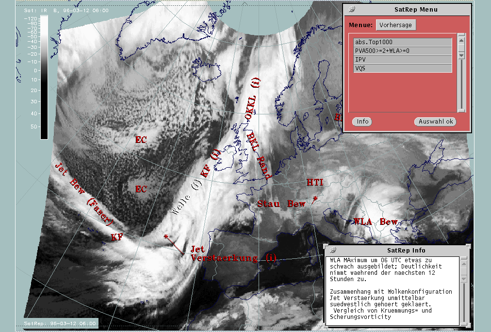
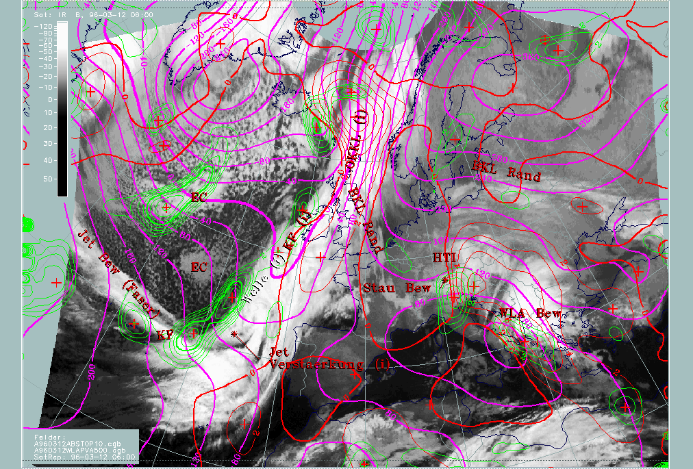
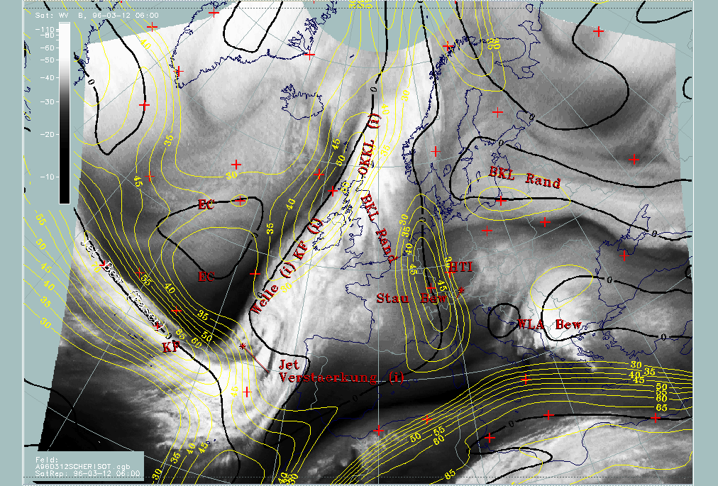
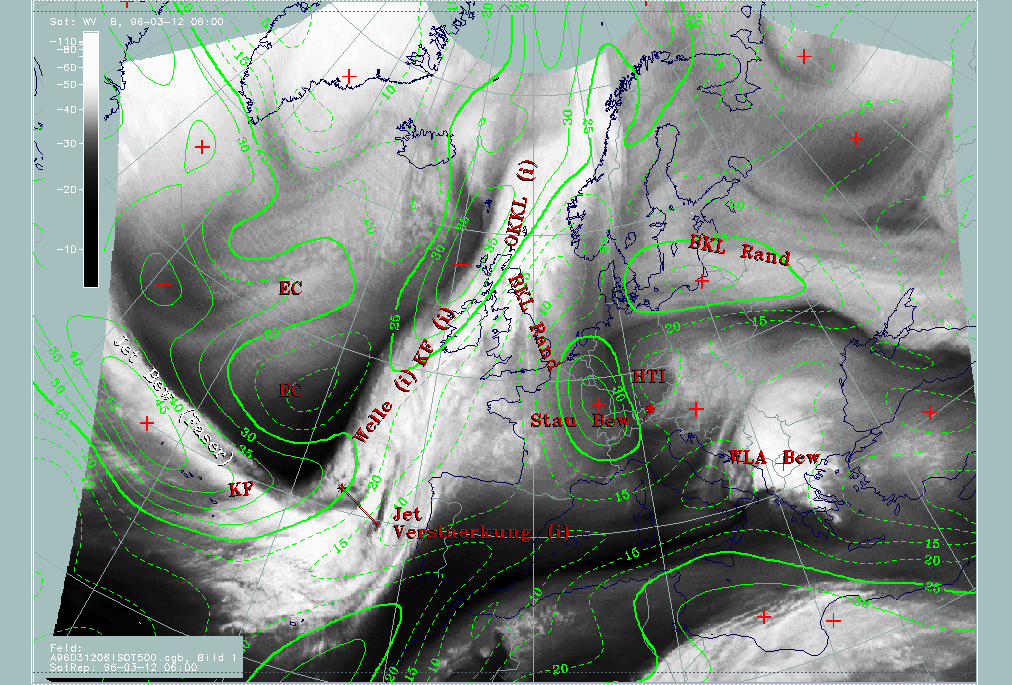
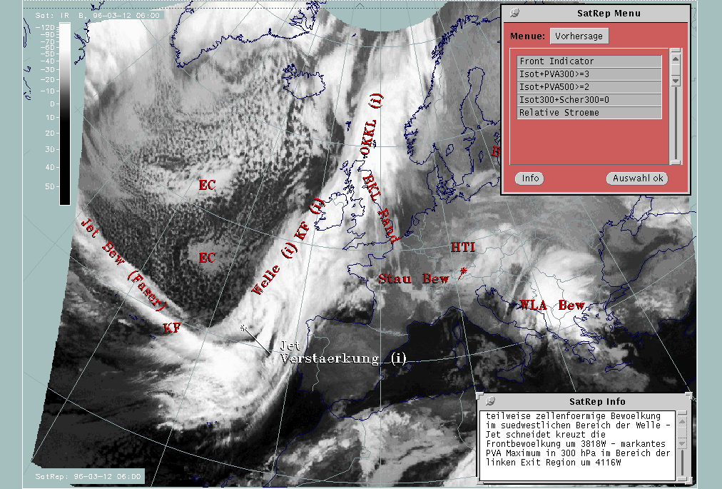
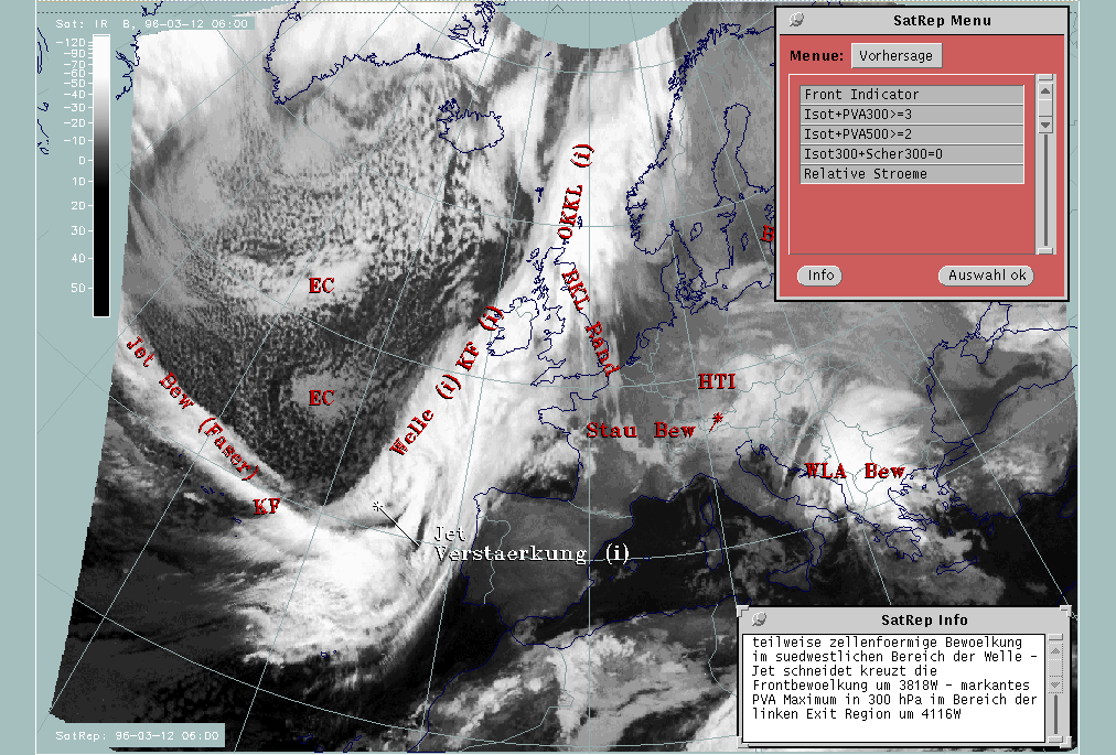
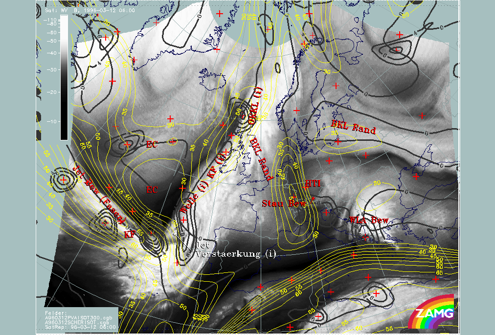
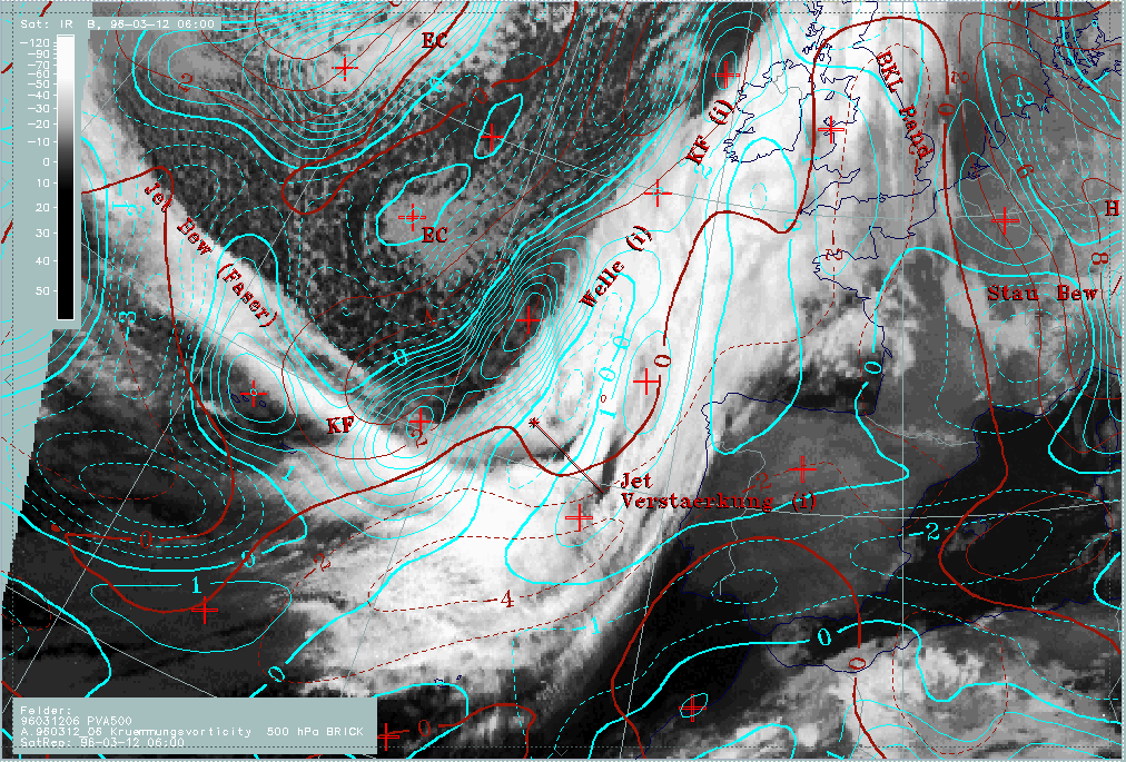
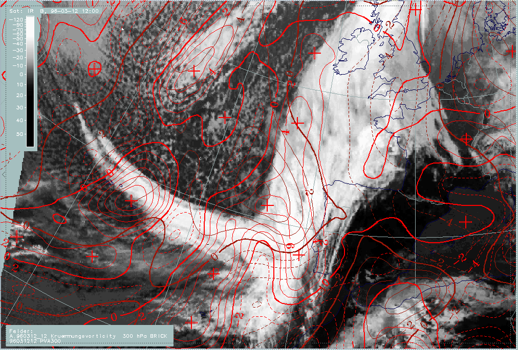
12 March 1996/06.00 UTC - Meteosat IR image; SatRep overlay: names of conceptual models
|
|
|
This case is dominated by a pronounced cloud band stretching from the Atlantic west of Portugal across the British Isles and further northwards to the Norwegian coast. At first sight it can be regarded as a Cold Front (abbreviation "KF"), but on closer inspection a number of substructures come to one's eyes.
- There is a bulge in the cloudiness south-west of Ireland (around 49N/15W) which may be indicative of a Wave ("Welle") centred immediately south of it.
- A very intensive feature is a narrow fibrous cloud band along 40N crossing the frontal cloud band almost perpendicularly; such a structure is indicative of a jet streak ("Jet Bew (Faser)") (compare Conceptual Models: Jet Cloudiness (Fibre) ).
- Cellular textured cloudiness within the Cold Front cloud band can be noticed immediately south of the Wave where the cloud fibre crosses the Cold Front band. Such a situation would be typical for an intensification of the frontal system by means of a jet streak crossing ("Jet Verstaerkung") (compare Conceptual Models: Front Intensification by Jet Crossing ).
- There is a cloud band structure with much warmer cloud tops, situated on the leading edge of the main cloud band. It reaches from south-east England south-eastwards into France and western Germany where it is connected with a spirally structured cloud system representing an upper level low (the band feature discussed here is named "BKL Rand") (compare Conceptual Models: Baroclinic Boundary ).
In the cold air over the Atlantic behind the Cold Front, intensive cellular cloudiness can be noticed with some areas of Enhanced Cumuli, especially around 52N/27W, and another one with much warmer tops around 46N/24W ("EC").
In this part of the study the Cold Front as a whole, the cloud band connected to the Upper Level Low and the Enhanced Cumuli are discussed, while the Wave and the intensification by a "jet streak crossing" will be discussed in the special investigation of this case study.
|
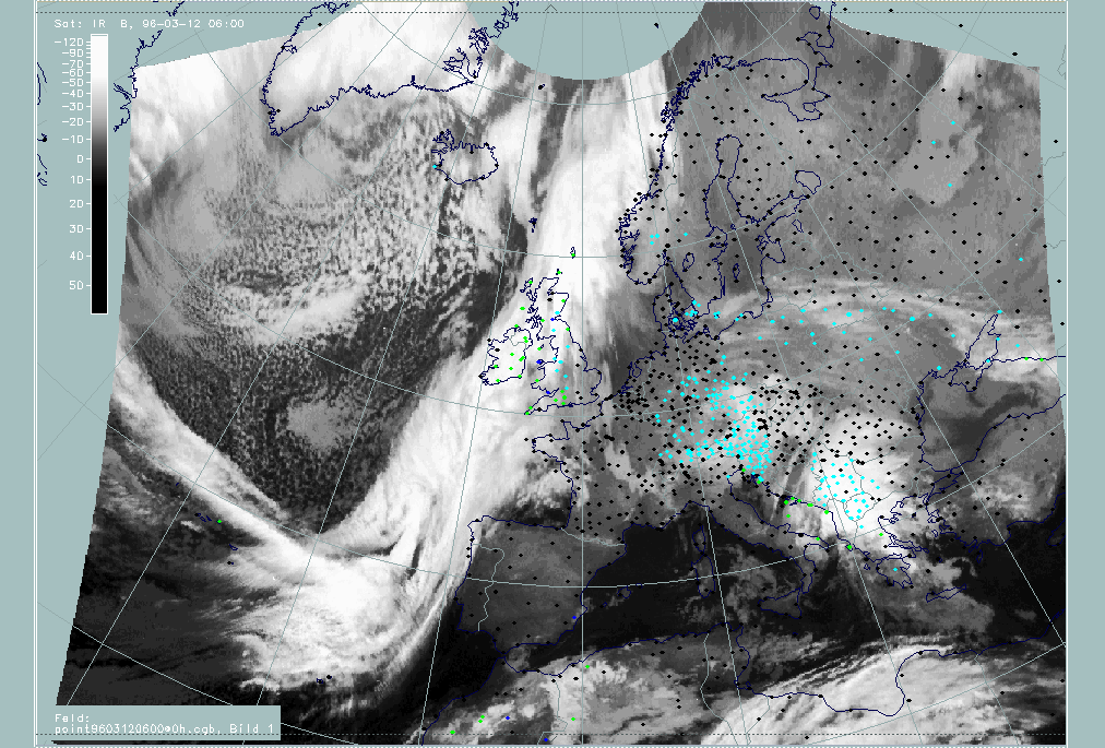
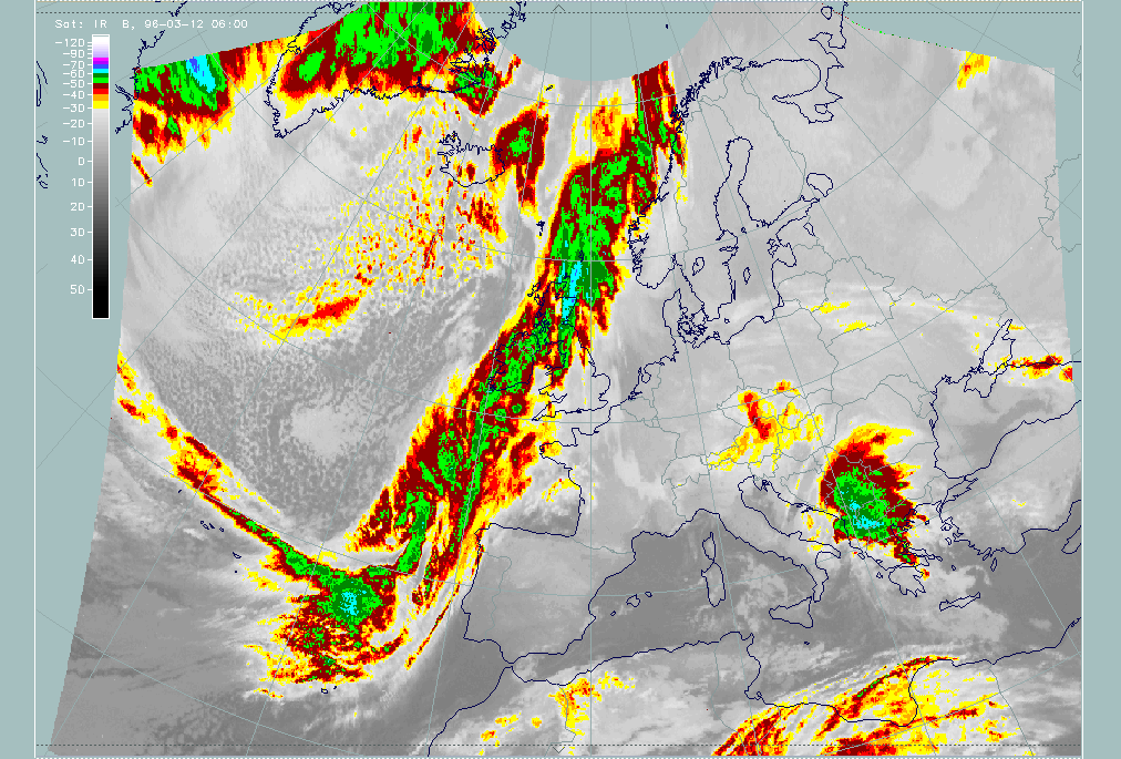
12 March 1996/06.00 UTC - Meteosat IR image; weather events (green: rain and showers, blue: drizzle, cyan: snow, purple: freezing rain,
red: thunderstorm with precipitation, orange: hail, black: no actual precipitation or thunderstorm with precipitation)
|
|
|
The demonstration of the weather intensity of the features under discussion is hindered by the fact that nearly all the cloud structures are located over the sea. Only the north-westernmost corner of Spain, Brittany and the British Isles can supply weather reports. From these it can be concluded that, except for a small stripe close to the leading edge of the cloud band, the rest of it is almost completely accompanied by precipitation. Increased weather events in the critical areas of the conceptual models "Wave" and "Front Intensification by Jet Crossing" compared to the surroundings cannot be observed because of their location over the sea.
18 - 19 February 1996 - Cold Front
|
12 March 1996/06.00 UTC - Meteosat IR image; SatRep overlay: names of conceptual models, SatRep menu: key parameters for Cold Front,
position of vertical cross section indicated
|
|
|
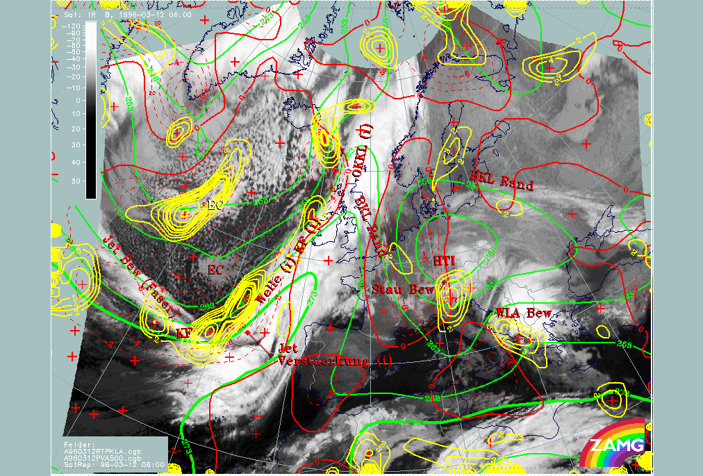
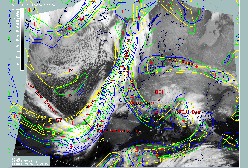
For the diagnosis of the physical state of the Cold Front, a couple of key parameters and useful key parameter combinations are available which were chosen with respect to the conceptual model (for more information compare Conceptual Models: Cold Front ).
| Front Indicator | This is a line indicating the maximum of the thermal front parameter (TFP) 500/850 hPa (*10-1Km-1) |
|---|---|
| TFP + rel.Top + TA>=0 | This is a combination of the thermal front parameter (TFP) greater than 3 units, the equivalent thickness (rel.Top) 500/850 hPa (K) and warm advection (TA>=0) (K 12h-1); this combination of key parameters is especially indicative of the thermal characteristics of a Cold Front |
| TFP + Scher300=0 | This is a combination of the thermal front parameter (TFP) 500/850 hPa greater than 3 units and the zero line of shear vorticity at the 300 hPa level (Scher300=0); this combination of key parameters is indicative of the relation between front and jet stream |
| Abs.Top500 + 1000 | This is the combination of height contours at 1000 and 500 hPa (gpm); this combination of key parameters is indicative of the stream and pressure distribution near the surface and in the middle of the troposphere |
| PVA500>=2 | This parameter shows maxima of positive vorticity advection (PVA) at 500 hPa exceeding 2 units (*10-9sec-2); this key parameter indicates areas with increased possibility for more severe weather events because of increased vertical motion (compare Conceptual Models: Wave and Conceptual Models: Front Intensification by Jet Crossing ) |
| Relative Stroeme (relative streams) | This parameter shows relative streams on isentropic surfaces; relative streams are indicative of the different air masses involved in the process and of areas with sinking or rising motion; they can be used to explain cloud configurations requiring special explanation |
| VQS | Gives the location of available vertical cross sections (VQS) |
|
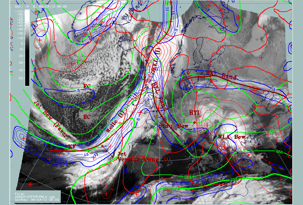
12 March 1996/06.00 UTC - Meteosat IR image; red thick: front indicator, blue: thermal front parameter (TFP) 500/850 hPa, green:
equivalent thickness 500/850 hPa, red: temperature advection - WA 1000 hPa, SatRep overlay: names of conceptual models
|
|
|
The TFP (thick red line) is ahead of a zone of high thickness gradients and close to the rear side of the cloud band, except for the Wave area where the typical cloud bulge exists. Over the Atlantic south of the Wave, the cloud band is under the influence of CA with the zero line of temperature advection close to the leading edge of the cloud band; north of the wave over Scotland the zero line accompanies the rear edge of the cloud band which therefore undergoes WA. So, concerning temperature advection, there are two different stages in the Cold Front separated by a Wave area. The southern part could also be diagnosed as a Cold Front in CA.
|
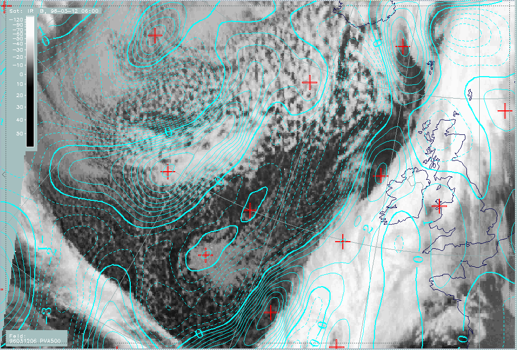
12 March 1996/06.00 UTC - Meteosat IR image; red thick: front indicator, red: height contours 1000 hPa, green: height contours 500 hPa,
yellow: positive vorticity advection (PVA) 500 hPa, position of vertical cross section indicated
|
|
|
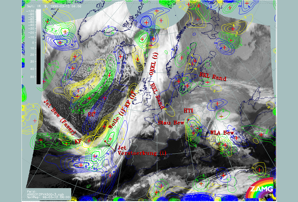
Height levels at 1000 hPa (red) and 500 hPa (green) show a well-developed frontal situation with a pronounced small scale surface trough indicating the surface frontline. A broader upper level trough with two superimposed small scale troughs is situated at the rear side of the frontal cloud band. Of the latter, the eastern one can be localized immediately behind the Cold Front cloud band, the western one in the area of Enhanced Cumuli ("EC").
Yellow isolines enclose maxima of PVA at 500 hPa and show the high values close to the rear edge, especially in connection with the southern part of the cloud band. This situation will be discussed in detail in the special investigation (compare Diagnosis for 12 March 06.00 UTC ). Another dominant area is connected with the EC over the Atlantic and will be discussed as a separate conceptual model (compare Enhanced cumulus ).
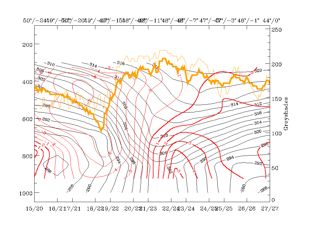
Another important tool for a deeper diagnosis of the Cold Front structure is vertical cross sections. In the first satellite image in this part the vertical cross section has been superimposed as a section line. It is in the region of the Wave bulge.
|
12 March 1996/06.00 UTC - Vertical cross section; black: isentropes (ThetaE), red thick: temperature advection - WA, red thin:
temperature advection - CA, orange thin: IR pixel values, orange thick: WV pixel values
|
12 March 1996/06.00 UTC - Vertical cross section; black: isentropes (ThetaE), blue: relative humidity, orange thin: IR pixel values,
orange thick: WV pixel values
|
|
|
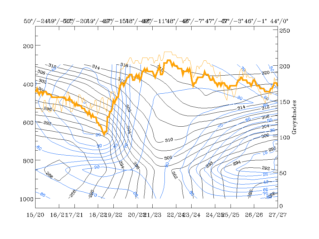
The isentropes (black lines in the first three panels) show a pronounced zone of high gradients typical for frontal situations. However, because of the location of the cross section line in the area of a Wave bulge, the configuration is a bit more complex and has to be explained in more detail. There is a broad zone of high gradients on the western (left) boundary of the cross section between approximately 650 and 300 hPa which is inclined downwards to the ground surface. The 302K isentropic surface reaches the latter at gridpoint 21/23 at about 49N/11W, a point which is approximately in the middle of the cloud band in the main part of the cloud bulge of the Wave. A second branch within this broad zone of high gradients is bound by the 304 - 310K isentropes and does not reach the ground surface. Instead, it forms a trough with an eastern branch inclined upward again. This is a synoptic situation typical for a Warm Front having no distinct surface front.
This configuration seems to be the consequence of the Wave area existing there and is confirmed by the other parameters to a certain extent. Humidity, for instance, contains high values of more than 90% reaching up to 500 hPa immediately ahead of the surface Cold Front and within and east of the trough in the isentropes and the Wave area. In contrast to this there is a steep gradient of humidity at about 49N/15W which coincides quite well with the western edge of the cloud band. This configuration has some similarities to the Kata Front type (compare Conceptual Models: Cold Front - Meteorological physical background ) where humidity and consequently cloudiness is ahead of the frontal surface, as opposed to the Ana Front type where it is inclined backwards on top of the frontal surface.
Looking at the vertical distribution of temperature advection, one can note a rather untypical situation, especially for the existence of a Wave: warm advection can only be found in front of the surface layer of the Cold Front and the Wave up to about 700 - 650 hPa, while above, there is pronounced cold advection. This would lead to the conclusion that Wave development is going on only in the lowest part of the troposphere and two different regimes are existing in two different layers, one on top of the other. Usually, such a vertical distribution with air becoming warmer in the lower layers but colder in the layers above is indicative of an unstable atmosphere. The character of cloudiness in the satellite images confirms this conclusion and, although not provable because of the location over the sea, convective weather events can be expected there.
|
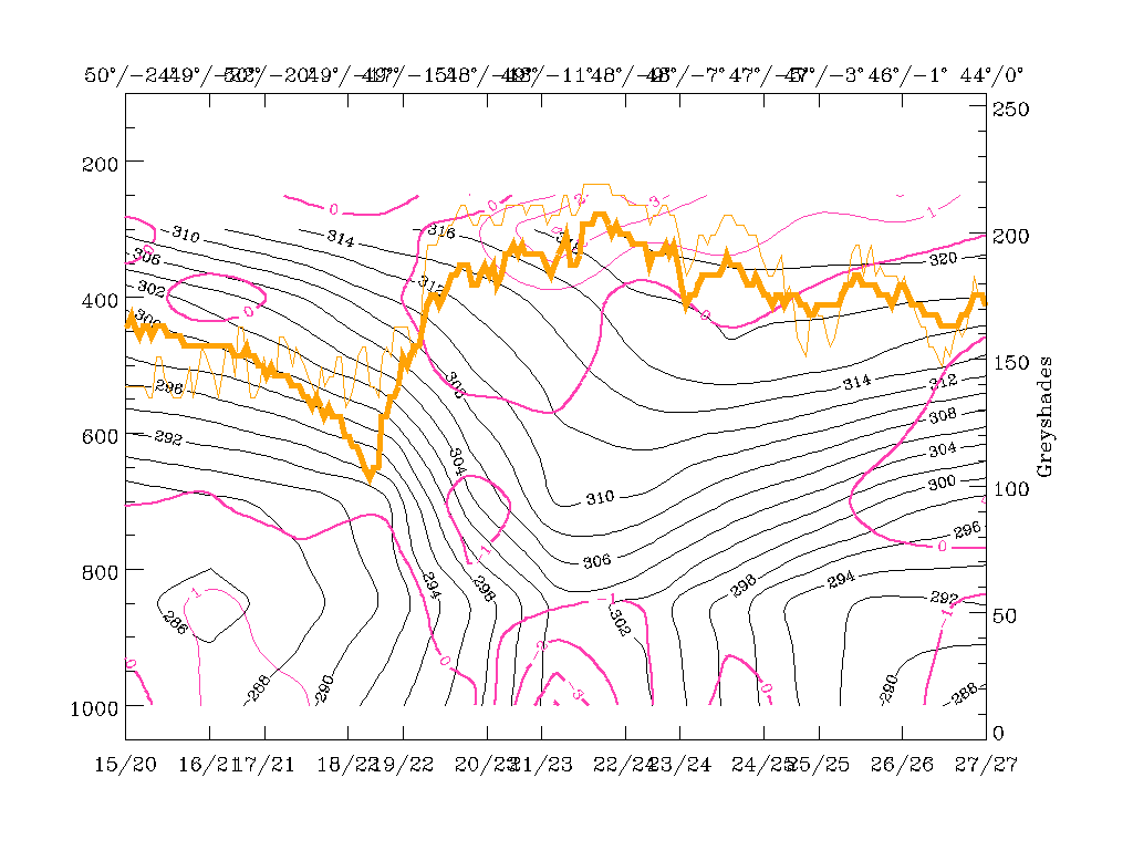
12 March 1996/06.00 UTC - Vertical cross section; black: isentropes (ThetaE), magenta thin: divergence, magenta thick: convergence,
orange thin: IR pixel values, orange thick: WV pixel values
|
12 March 1996/06.00 UTC - Vertical cross section; black: isentropes (ThetaE), magenta thin: divergence, magenta thick: convergence, cyan
thick: vertical motion (omega) - upward motion, cyan thin: vertical motion (omega) - downward motion, orange thin: IR pixel values,
orange thick: WV pixel values
|
|
|
The latter conclusion is also supported by two further parameters: divergence and vertical motion. There is a zone of convergence connected with the Cold Front surface with a primary maximum from the surface up to about 850 hPa and a secondary maximum around 700 hPa. As convergence and vertical motion are connected to each other via the Richardson equation, it is not surprising that maxima of upward motion exist on top of the maxima of convergence. This leads to a very typical distribution of the zone of convergence within the frontal zone, and a zone of upward motion on top of the frontal zone connected with cloudiness (compare, Conceptual Models: Cold Front - Typical appearance in vertical cross sections ). Nevertheless, in this case the intensity of vertical motion, especially in the Wave area, is extremely high, in accordance with the appearance of cloudiness there.
12 March 1996 - Baroclinic Boundary To Upper Level Low
The discussion of this cloud feature is not intended to be a complete diagnosis of a Baroclinic Boundary but includes some discussions about different types of Warm Fronts.
|
12 March 1996/06.00 UTC - Meteosat IR image; weather events (green: rain and showers, blue: drizzle, cyan: snow, purple:
freezing rain, red: thunderstorm with precipitation, orange: hail, black: no actual precipitation or thunderstorm with
precipitation)
|
|
|
The cloud feature can be identified as a band-like structure extending with cyclonic curvature from south England across Belgium and France to the Alps where it has some connection with a cloud spiral over Austria. It consists of cloudiness with lower tops which are non-precipitating.
|
12 March 1996/06.00 UTC - Meteosat IR image; red thick: front indicator, red: height contours 1000 hPa, green: height contours 500 hPa,
yellow: positive vorticity advection (PVA) 500 hPa, SatRep overlay: names of conceptual models, position of vertical cross section
indicated
|
12 March 1996/06.00 UTC - Meteosat IR image; red thick: front indicator, blue: thermal front parameter (TFP) 500/850 hPa, green:
equivalent thickness 500/850 hPa, red: temperature advection - WA 1000 hPa, SatRep overlay: names of conceptual models
|
|
|
The inspection of the height levels represented by 1000 hPa close to the surface and by 500 hPa in upper levels clearly shows that this cloud structure is in a transition area between the trough region of the front and a completely different regime east of it. This regime represents an intensive upper level low with a centre over south Germany, but in the lower surface level merely a stream from the east bending to the north in the area of the Baroclinic Boundary as well as the main Cold Front. As indicated by the yellow lines, there exists a maximum of PVA on the rear side of the band.
Although the cloudiness originates in the main cloud band, it cannot be analysed as a Warm Front because it leaves the influence of this synoptic regime very soon and becomes related to the south-western part of the huge Upper Level Low. This is clearly confirmed by the thickness and the TFP, (green and blue lines), which both show the cyclonic curvature connected with the Upper Level Low. This would be very untypical for a Warm Front connected with the main Cold Front.
Another parameter that supports this assumption is temperature advection (red lines). There is no WA maximum superimposed on the cloud band in front of the TFP but rather CA which is concentrated in the western and central part of the upper level low. WA can only be found within the main Cold Front band and, as is usual, on the eastern half of the Upper Level Low.
Consequently, this substructure connected with the main Cold Front band seems to be a separate cloud feature which is not predominately influenced by the physical state of the frontal system Instead, it forms the Baroclinic Boundary to the Upper Level Low, which of course is responsible for the formation of a distinct thickness gradient between the thickness ridge ahead of the main Cold Front and the minimum of the Upper Level Low. Cloudiness forming in this front - like zone undergoes the cyclonic circulation of the Upper Level Low.
12 March 1996 - Enhanced Cumulus
|
12 March 1996/06.00 UTC - Meteosat IR image; SatRep overlay: names of conceptual models, SatRep menu: key parameters for EC
|
|
|
Nearly the whole Atlantic area behind the Cold Front and north of the cloud fibre which crosses the Cold Front band (compare Diagnosis for 12 March 06.00 UTC ) is filled with typical cold air cloudiness in the form of regularly shaped cloud cells. They have lower and warmer tops in the southern parts but become wider and colder to the north. This is indicative of a bigger temperature difference between water and air, and of an increasing instability in this area.
There are two specific areas where the cells form continuous regions called "EC" (Enhanced Cumuli) (compare Conceptual Models: Enhanced Cumulus ): the main one is an elongated area around 52N/28W; a second, smaller one with untypically warm cloud tops can be identified to the south, at 46N/23W. In addition to the state of the atmosphere characteristic for the formation of cold air cloud cells, maxima of PVA exist which indicate the propagation of a small scale trough or a jet streak.
As can be seen in the SatRep Menu window, the characteristic key parameters and key parameter combinations are:
| Rel.Top. + TA=<0 | This combination gives an overview of the bigger scale situation; typically ECs can be found within the thickness troughs on the rear of the Cold Fronts mostly within cold advection (CA) (K12h-1) |
|---|---|
| PVA500>=2 | Positive vorticity advection (PVA) exceeding a threshold of 2 units (*10-9sec-2) at 500 hPa; well-developed cases show up with pronounced PVA maxima which can also be followed prognostically |
| Isot + PVA300>=3 | This is a combination of isotachs at 300 hPa greater than 30 units (ms-1) and positive vorticity advection (PVA) at 300 hPa exceeding 3 units (*10-9sec-2); this combination indicates a special situation where ECs can develop, namely in the left exit region of jet streaks |
|
12 March 1996/06.00 UTC - Meteosat IR image; red thick: front indicator, red: temperature advection - CA 1000 hPa, green: equivalent
thickness 500/850 hPa, yellow: positive vorticity advection (PVA) 500 hPa; SatRep overlay: names of conceptual models
|
|
|
The combination of thickness (white) and temperature advection (red) shows first of all the typical synoptic scale structure with both a main thickness trough and a big area of cold advection (dashed red lines) in the area of ECs. In this special case thickness contains also a fine scale structure with two small scale troughs superimposed upon the synoptic scale trough exactly where the ECs exist. The yellow lines show maxima of positive vorticity advection at 500 hPa exceeding a threshold of 2 units. The bigger, brighter and more north-western EC is under the influence of pronounced PVA, while the EC with the warmer tops is not connected with isolines. But the latter statement is only a consequence of the chosen threshold; taking into account the whole field of vorticity advection at 500 and 300 hPa clearly reveals that there is a second relative maximum of PVA related to the EC with the warmer tops. Both PVA maxima indicate the approach of small scale upper level troughs and the advection of curvature vorticity.
|
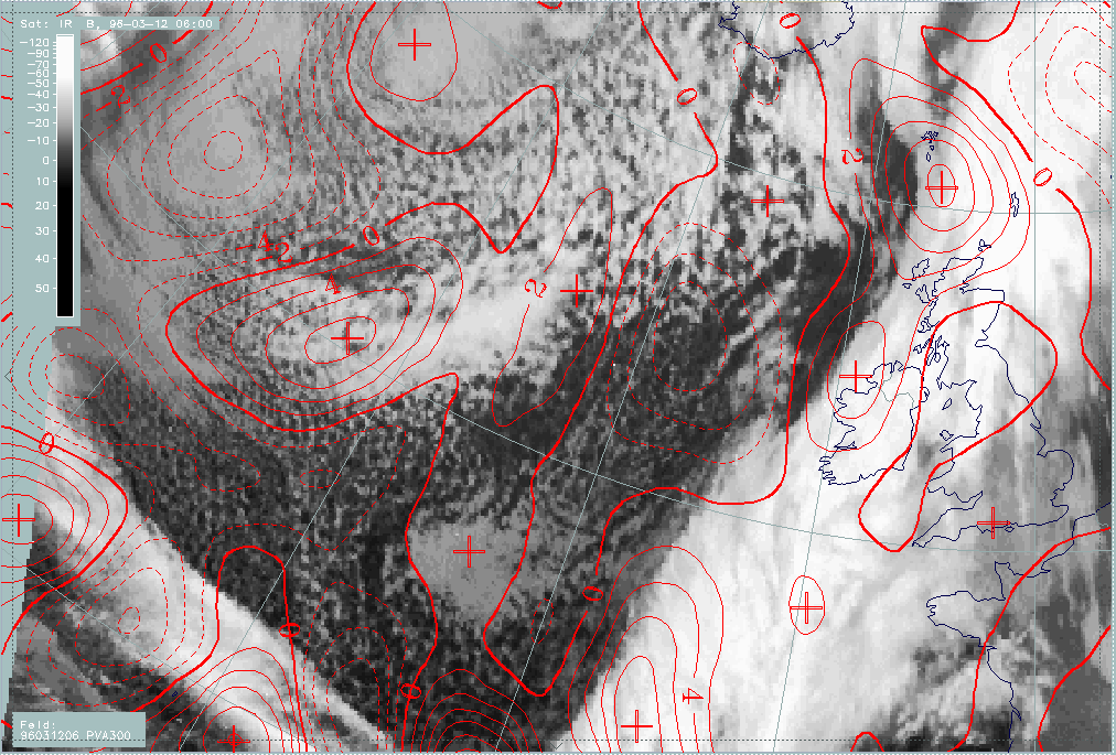
12 March 1996/06.00 UTC - Meteosat IR image; cyan: positive vorticity advection (PVA) 500 hPa
|
12 March 1996/06.00 UTC - Meteosat IR image; red: positive vorticity advection (PVA) 500 hPa
|
|
|
PVA maxima in connection with EC cloudiness show that there is additional rising caused by the contribution of PVA to the Omega-equation. In this context it should be repeated (compare Conceptual Models: Enhanced Cumulus - Meteorological physical background ) that from the theoretical point of view it is not the maximum of PVA in upper levels that causes upward motion but the increase of vorticity advection with height; from the practical point of view and the experience in satellite meteorology, the PVA maxima restricted to the upper levels can be inspected if an increase of wind speed with height is assumed. This assumption is a reasonable one which can be supported by experience from vertical cross sections; nevertheless there might be cases where it is not fulfilled.
Experience in satellite meteorology furthermore shows that those PVA maxima at 500 and/or 300 hPa are very appropriate for a forecast of EC cloudiness during the next 12 hours (compare Forecast for Enhanced Cumulus ).
12 March 1996 - Cold Front And Baroclinic Boundary To Upper Level Low
|
12 March 1996/06.00 UTC - Meteosat IR image; SatRep overlay: names of conceptual models, SatRep menu: key parameters for Cold Front
forecast
|
|
|
Concerning the forecast of the conceptual model "Cold Front" in the SatRep Menu a button "Vorhersage = forecast" has to be clicked on, then the relevant menu appears. As can be seen in the right upper corner, two kinds of forecasts and forecast times are presented:
The very short range forecast VSRF (06.00 - 18.00 UTC, 12 hours)
For the very short range forecast, six-hourly forecasts from ECMWF are used. Those parameters which are key parameters of a conceptual model are prepared as overlays on the satellite image in three different colours representing the three points of time 06.00, 12.00 and 18.00 UTC:
- yellow: 06.00 UTC
- green: 12.00 UTC
- blue: 18.00 UTC
In the case of the conceptual model "Cold Front", the thermal front parameter (TFP) and maxima of positive vorticity advection (PVA500>=2 units) are taken into account.
Nowcasting (0-2 hours)
For this forecast time, atmospheric motion vectors (AMVs) are used which extrapolate the cloud systems for the next two hours. These nowcasts are renewed half-hourly or hourly and are not discussed here.
|
12 March 1996/06.00 UTC - Meteosat IR image; yellow: thermal front parameter (TFP) 500/850 hPa 06.00 UTC, green: thermal front
parameter (TFP) 500/850 hPa 12.00 UTC, blue: thermal front parameter (TFP) 500/850 hPa 18.00 UTC
|
|
|
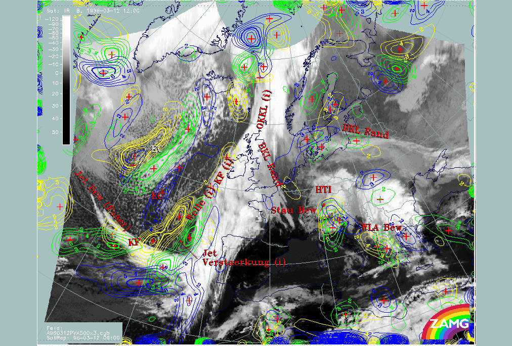
The most important parameter in this case is the forecast of the TFP. There is a rather fast displacement of the part of the front south of the Wave, which means that the front reaches the Spanish west coast and Portugal at 18.00 UTC. As mentioned for 06.00 UTC (compare Cold Front ) the TFP in this part is close to the rear side of the cloud band, which means for the forecast that Portugal should already be under the influence of the frontal cloud band by this time. This fast moving southern part is an area where Wave and jet intensification take place and therefore it is also discussed in the "special investigation" (compare Diagnosis for 12 March 06.00 UTC ).
North of the Wave the front is nearly stationary, especially above the British Isles. Further north of Scotland the formation of an Instant Occlusion process, which is not discussed here, leads to a north-westerly movement again.
The Baroclinic Boundary reaching from the British Isles into the Mediterranean and forming the southern boundary of the Upper Level Low is stationary during the next 12 hours, which is expected considering the stationary state of the Upper Level Low. Only in the south-eastern part is a small shift recognizable.
|
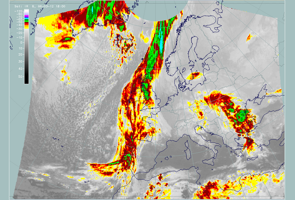
12 March 1996/06.00 UTC - Meteosat IR enhanced image
|
12 March 1996/12.00 UTC - Meteosat IR enhanced image
|
|
|
|
|
|
12 March 1996/18.00 UTC - Meteosat IR enhanced image
|
|
The images of the three points in time confirm this as a very good forecast.
12 March 1996 - Forecast For Enhanced Cumulus
|
12 March 1996/06.00 UTC - Meteosat IR image; SatRep overlay: names of conceptual models, SatRep menu: key parameters for EC forecast
|
|
|
Concerning the forecast of the conceptual model "EC" in the SatRep Menu a button "Vorhersage = forecast" has to be clicked on, then the relevant menu appears. As can be seen in the right upper corner, two kinds of forecasts and forecast times are presented:
The very short range forecast VSRF (06.00 - 18.00 UTC, 12 hours)
For the very short range forecast, six-hourly forecasts from ECMWF are used. Those parameters which are key parameters of a conceptual model are prepared as overlays on the satellite image in three different colours representing the three points of time 06.00, 12.00 and 18.00 UTC:
- yellow: 06.00 UTC
- green: 12.00 UTC
- blue: 18.00 UTC
In the case of the conceptual model "EC", the PVA at 500 hPa exceeding the threshold of 2 units, as well as the combination of isotachs and PVA at 300 hPa exceeding a threshold of 3 units, are taken into account.
The PVA at 500 hPa is more indicative of situations representing an approaching trough and curvature vorticity, while at 300 hPa the PVA is more indicative of a propagating jet streak and shear vorticity.
Nowcasting (0-2 hours)
For this forecast time, atmospheric motion vectors (AMVs) are used which extrapolate the cloud systems for the next two hours. These nowcasts are renewed half-hourly or hourly and are not discussed here.
|
12 March 1996/06.00 UTC - Meteosat IR image; yellow: positive vorticity advection (PVA) 500 hPa 06.00 UTC, green: positive vorticity
advection (PVA) 500 hPa 12.00 UTC, blue: positive vorticity advection (PVA) 500 hPa 18.00 UTC; SatRep overlay: names of conceptual
models
|
|
|
There is a distinct displacement of the elongated PVA lobe at 500 hPa to the south-west, but on the other hand also a continuing elongation of the lobe can be observed; consequently it is not so easy to forecast the maximum of EC cloudiness in relation to the forecast EC lobe. In the 06.00 UTC image the EC is more connected with the southern maximum of PVA, therefore this propagation will be of most interest. For 18.00 UTC the elongated lobe is split into two maxima: one in the south, which should be the relevant one for the forecast of the EC in the 06.00 UTC image, and another one in the north close to Iceland.
|
12 March 1996/12.00 UTC - Meteosat IR image; yellow: positive vorticity advection (PVA) 500 hPa 06.00 UTC, green: positive vorticity
advection (PVA) 500 hPa 12.00 UTC, blue: positive vorticity advection (PVA) 500 hPa 18.00 UTC; SatRep overlay: names of conceptual
models
|
12 March 1996/18.00 UTC - Meteosat IR image; yellow: positive vorticity advection (PVA) 500 hPa 06.00 UTC, green: positive vorticity
advection (PVA) 500 hPa 12.00 UTC, blue: positive vorticity advection (PVA) 500 hPa 18.00 UTC; SatRep overlay: names of conceptual
models
|
|
|
The images of 12.00 and 18.00 UTC overlaid by the PVA maxima forecast show a perfect correspondence between the PVA field and the cloudiness. A decrease of cloudiness between 12.00 and 18.00 UTC can be recognized.
As shown for 06.00 UTC (compare Enhanced Cumulus ) the second, warmer EC cloud could only be explained with help of the complete field of VA at 500 as well as at 300 hPa; consequently they are superimposed also on the 12.00 UTC image. Both levels still contain this secondary relative maximum, but weakened in comparison to 06.00 UTC. The rest of the cloudiness of this second EC can be found in the region of the secondary PVA maxima. By 18.00 UTC the phenomenon has disappeared.
|
12 March 1996/12.00 UTC - Meteosat IR image; cyan: positive vorticity advection (PVA) 500 hPa
|
12 March 1996/12.00 UTC - Meteosat IR image; red: positive vorticity advection (PVA) 300 hPa
|
|
|
So this case study is a good example for three characteristics:
- There is excellent correspondence between EC cloudiness and PVA maxima, indicating the importance of the PVA field as a key parameter for the physical processes being described by this conceptual model;
- There is an excellent forecast of the PVA maxima;
- There is some indication about the possibility of a forecast of EC dissolution from the intensity difference between the two EC areas as well as from the intensity decrease in the forecast. But this latter point is more difficult to use because there are no thresholds of PVA weakening that could be used for a decision about a probable weakening of such a phenomenon.
12 March 1996 - Diagnosis 12 March 06.00 UTC
In this chapter the following points of interest will be discussed:
- Wave
- Cloud Fibre at jet axis
- Intensification of Cold Front through jet crossing
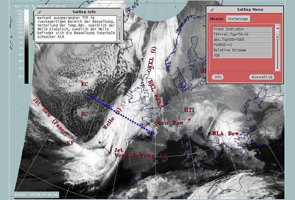
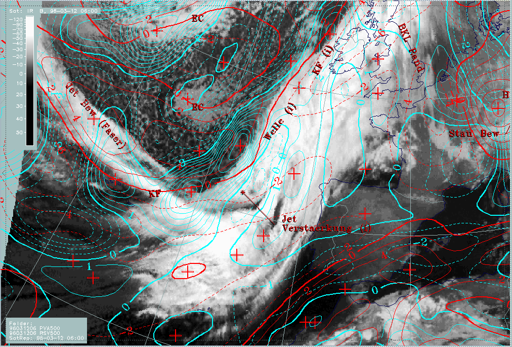
Diagnosis of conceptual model "Wave": 12 March 1996/06.00 UTC
|
12 March 1996/06.00 UTC - Meteosat IR image; SatRep overlay: names of conceptual models, SatRep menu: key parameters for Wave
|
|
|
For the diagnosis of the physical state of the conceptual model "Wave" a couple of key parameters and useful key parameter combinations are available which were chosen with respect to the conceptual model (for more information compare Conceptual Models: Wave ).
| ABSTOP1000 + PVA500>=2 + WLA | This is a commonly used combination of three parameters typically indicative of a wave:
|
|---|---|
| PV | Represents isentropic potential vorticity (*10-6m2Ksec-1kg-1) on several levels |
| VQS | Gives the location of available vertical cross sections (VQS) |
In the case of a well-developed wave, the satellite image shows a cloud bulge towards the cold air which indicates the cyclonic circulation and consists of thick intensive cloudiness. This is a result of upward motion caused by several processes of which PVA indicates only one. In this particular case, the cloud bulge in the area of the analysed Wave is rather weak. Consequently, the written information in the window addresses two points:
- WA is not very well developed for 06 UTC but becomes more distinct during the next two hours.
- The connection with the "Front Intensification by Jet Crossing" immediately south of it should be clarified.
|
12 March 1996/06.00 UTC - Meteosat IR image; magenta: height contours 1000 hPa, green: positive vorticity advection (PVA) 500 hPa, red:
warm advection 1000 hPa; SatRep overlay: names of conceptual models
|
12 March 1996/06.00 UTC - Meteosat IR image; yellow: warm advection 1000 hPa 06.00 UTC, green: warm advection 1000 hPa 12.00 UTC, blue:
warm advection 1000 hPa 18.00 UTC; SatRep overlay: names of conceptual models
|
|
|
The parameter combination in the left image indicates that the state of the atmosphere is very similar to a state typical for Wave development: there is a pronounced trough in the surface field very close to the rearward edge of the cloud bulge and a zone of two PVA maxima at 500 hPa immediately behind the cloudiness. Considering the cloud configuration, it should be the northern of the two PVA maxima that belongs to the Wave situation. While this PVA maximum is somewhat too far behind the cloud bulge compared to a classical Wave situation, the WA maximum south-west of Cornwall is too far to the north-east and also rather weak compared to classical situations (compare Conceptual Models: Wave ). The forecast of the WA field for the next 12 hours (right image) confirms that WA is still active in the area of interest and becomes even more distinct.
Consequently, this is an example where key parameters clearly indicate the existence of the conceptual model "Wave" but either the situation is weak and/or in an initial stage, or the numerical model does not reproduce the situation correctly, probably because of a lack of data over the Atlantic. So this is an example where the knowledge about a conceptual model can be used to interpret an uncertain, or even incorrect, numerical model, considering the actual cloud configuration in the satellite image.
For further development and a more detailed analysis with respect to the "Front Intensification" to the south, look at the relevant sections of "forecast" and "discrimination" within this chapter.
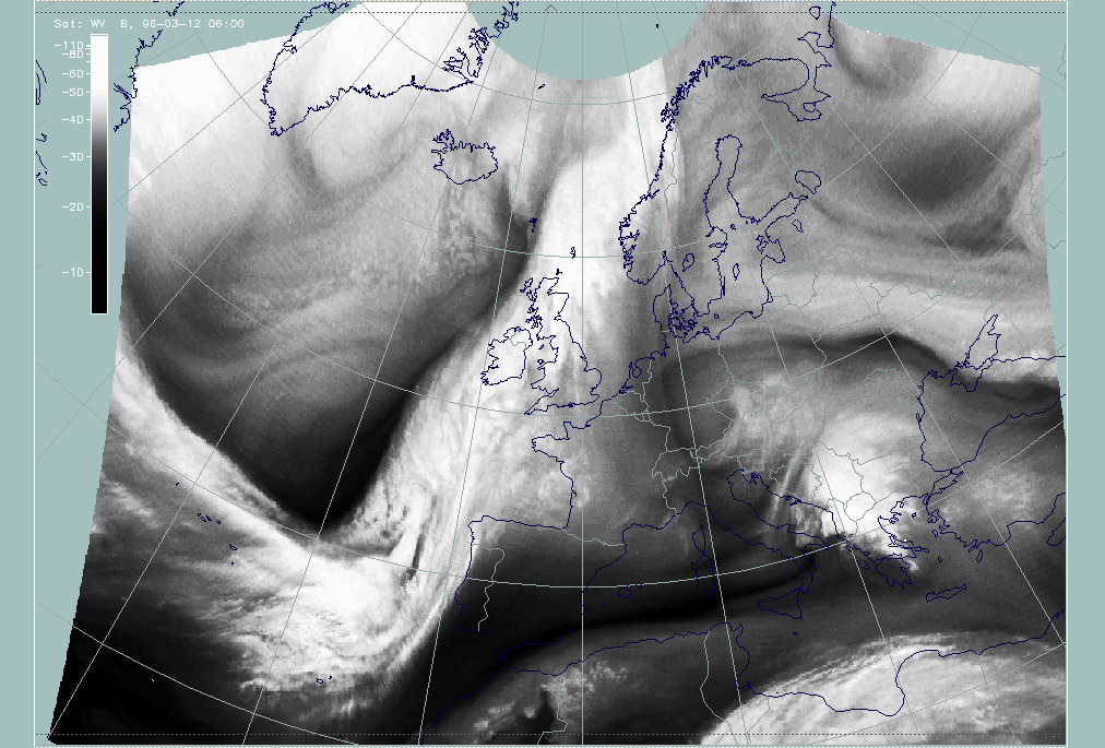
Diagnosis of "Cloud Fibre at Jet Axis" for 12 March 06.00 UTC
|
12 March 1996/06.00 UTC - Meteosat IR image; SatRep overlay: names of conceptual models, SatRep menu: key parameters for Cloud Fibre
|
12 March 1996/06.00 UTC - Meteosat WV image
|
|
|
For the diagnosis of the physical state of the conceptual model "Cloud Fibre at Jet Axis" a couple of key parameters and useful key parameter combinations are available which were chosen with respect to the conceptual model (for more information compare Conceptual Models: Jet Cloudiness (Fibre) ).
| Isot300 + Scher300=0 | This is the combination of isotachs at 300 hPa greater than 30 units (msec-1) representing the jet stream and jet streaks at a level which is very representative for jets, and the zero line of shear vorticity which marks the jet axis according to the definition of a jet |
|---|---|
| UTH | Upper tropospheric humidity (%), a parameter that is derived from the WV imagery and can in addition to the WV imagery emphasize the dry stripes on the cyclonic side of the jet streak |
It is well known that narrow Cloud Fibres consisting of only high cloudiness can develop close to the jet axis, but only on its anticyclonic side (compare Conceptual Models: Jet Cloudiness (Fibre) ). In this case a very well-developed situation is presented. The Cloud Fibre extends across the Atlantic approximately from 43N/40W nearly perpendicular to the frontal cloud band. It is rather broad compared to other cases and structured, which can be interpreted as the consequence of different effects at different height levels. The WV image shows a distinct Black Stripe on the cyclonic side of the cloud structure.
|
12 March 1996/06.00 UTC - Meteosat WV image; yellow: isotachs 300 hPa, black: shear vorticity 300 hPa; SatRep overlay: names of
conceptual models
|
|
|
There is an intensive jet streak with wind speeds up to 70 m sec-1 (yellow lines) exactly in the part of the cloud fibre that can be seen over the Atlantic. The zero line of shear vorticity (black line) is not exactly at the northern boundary of the fibre but very close to it, and moves from the northern boundary in the west to a more southern fibre close to the frontal cloud band. This can again be interpreted as an effect of different heights.
|
12 March 1996/06.00 UTC - Meteosat WV image; green: isotachs 500 hPa; SatRep overlay: names of conceptual models
|
|
|
The isotachs at 500 hPa show a jet streak in this area too, but it is tilted relative to the 300 hPa streak as well as shifted southward. This underlines the fact that there are cloud-producing processes in several levels which lead to the existence of a substructure in the fibre. The resolution of the numerical model available is not adequate for detecting these different structures.
The whole situation is not only indicative of the existence of a jet streak and the orientation of its axis, but also of some interaction between this streak and the frontal cloud band. This is discussed as the next topic.
Diagnosis for conceptual model "Front Intensification by Jet Crossing" for 12 March 06.00 UTC
|
12 March 1996/06.00 UTC - Meteosat IR image; SatRep overlay: names of conceptual models, SatRep menu: key parameters for Jet
Intensification
|
|
|
The following key parameters and their combinations are regarded as relevant for the conceptual model "Front Intensification by Jet Crossing" (in short form "Jet Intensification"):
| Front Indicator | This is a line indicating the maximum of the thermal front parameter (TFP) 500/850 hPa (*10-1Km-1) |
|---|---|
| Isot + PVA300>=3 | This is a combination of isotachs at 300 hPa greater than 30 units (m sec-1) and positive vorticity advection (PVA) at 300 hPa exceeding 3 units (*10-9sec-2) |
| Isot + PVA500>=2 | This is a combination of isotachs at 500 hPa greater than 30 units (m sec-1) and positive vorticity advection (PVA) at 500 hPa exceeding 2 units (*10-9sec-2); both parameter combinations locate the exit region and the PVA maximum in relation to the frontal cloud band |
| Isot300 + Scher300=0 | This parameter combination shows the isotachs at 300 hPa greater than 30 units (m sec-1) and the zero line of shear vorticity which marks the jet axis; one can get information about the existence and strength of jet streaks and the course of the jet axis |
| Relative Stroeme (relative streams) | This parameter shows relative streams on isentropic surfaces; relative streams are indicative of the different air masses involved in the process and of areas of sinking or rising motion; they can be used to explain cloud configurations requiring special explanation |
The satellite image shows a cloud area with a distinct lumpy structure within the frontal cloud band immediately north of the crossing jet fibre. This is a cloud feature which typically represents increased frontal cloudiness and intensity in the left exit region of a jet streak which is superimposed on the cloud band (compare Conceptual Models: Front Intensification by Jet Crossing ). The information contained in the window draws attention to this area.
|
12 March 1996/06.00 UTC - Meteosat WV image; yellow: isotachs 300 hPa, black: positive vorticity advection (PVA) 300 hPa, black: shear
vorticity 300 hPa; SatRep overlay: names of conceptual models
|
|

|
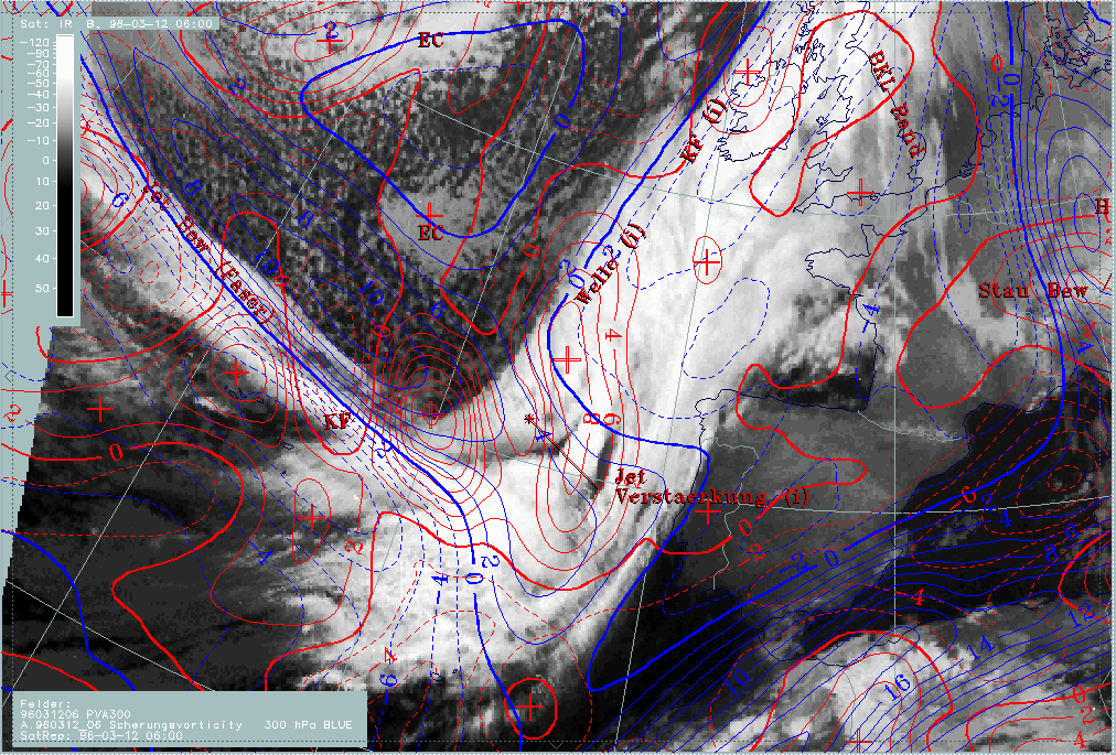
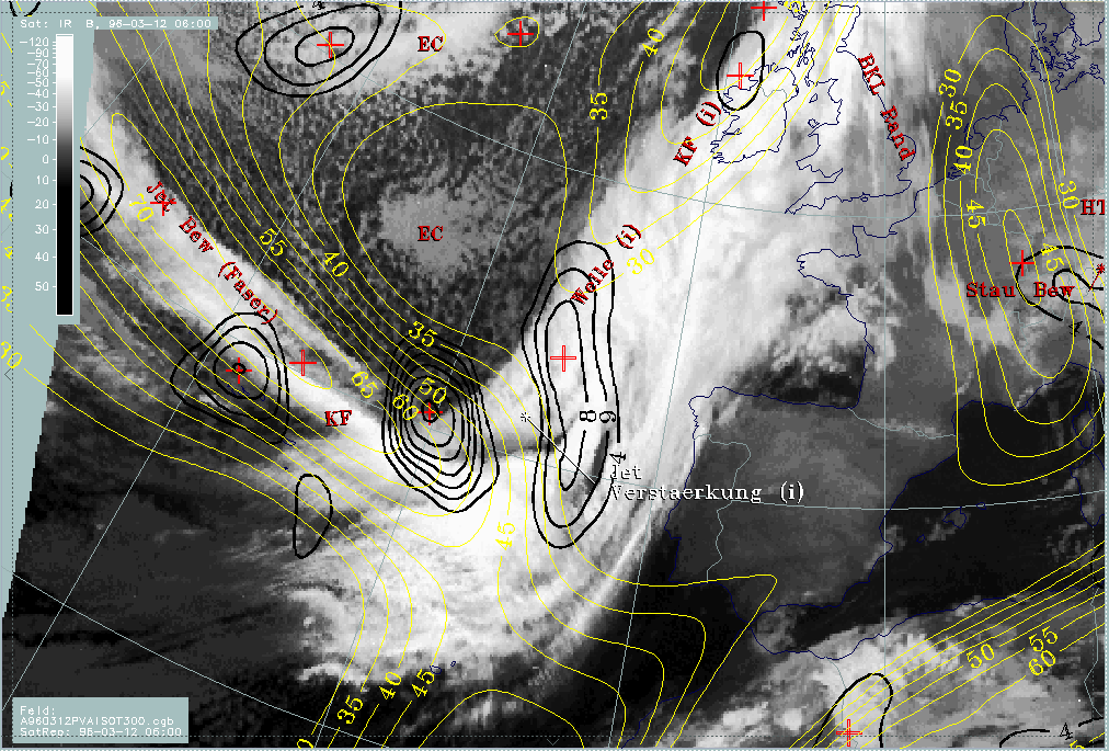
The isolines are a combination of the key parameter combinations "isotachs (yellow lines) and PVA at 300 hPa (black lines forming circular and elliptical areas)" as well as "isotachs and zero line of shear vorticity (long black lines)". The correspondence of the indicated cloud area with a PVA maximum in the left exit region is not as clear as could be expected from the cloudiness alone. There are two separate PVA maxima in the left exit region exceeding the threshold of 4 units: one is close to the jet axis around 40N/20W and a second one stretches from about 48N/15W southward to 38N/14W.
Although both maxima are in the left exit region of the jet streak there is no good correspondence with the cloud mass of the "Jet Intensification". The western maximum is located too far to the south-west of the relevant increased cloud area, and the eastern one splits into two maxima with the northern one very close to the Wave area and the southern one east of the increased cloud area of the "Jet Intensification".
Because of the close proximity of cloudiness belonging on the one hand to the Wave and on the other hand to the Jet Intensification, this situation should be clarified in more detail with help of additional parameters. The aim of this special investigation is to find out if different conceptual models can be separated, which is necessary especially for the forecast, and/or if model errors can be detected. These investigations are described in the next section.
12 March 1996 - Discrimination Between Conceptual Models "Wave" And "Front Intensification By Jet Streak Crossing"
|
12 March 1996/06.00 UTC - Meteosat IR image; SatRep overlay: names of conceptual models, SatRep menu: key parameters for Wave
|
12 March 1996/06.00 UTC - Meteosat IR image; SatRep overlay: names of conceptual models, SatRep menu: key parameters for Jet
Intensification
|

|
|
The diagnosis has shown that the conceptual models "Wave" and "Front Intensification by Jet Crossing" (short: "Jet Intensification"), which represent substructures within frontal cloud bands, are very close together; key parameter distributions, especially PVA maxima, do not clearly separate these areas. Consequently, additional parameters that go into more detail are useful for a special investigation.
Appropriate key parameters are curvature and shear vorticity which should be able to distinguish between effects from circulation and from jet streaks; the first are regarded as more dominant for a Wave, the latter as more dominant for Front Intensification cases.
|
12 March 1996/06.00 UTC - Meteosat WV image; yellow: isotachs 300 hPa, black: positive vorticity advection (PVA) 300 hPa, black: shear
vorticity 300 hPa; SatRep overlay: names of conceptual models
|
|
|
|
|
|
|
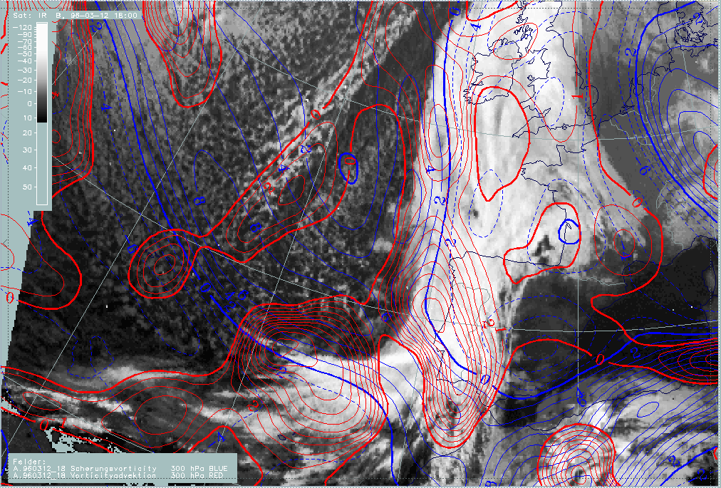
12 March 1996/06.00 UTC - Meteosat IR image; red: positive vorticity advection (PVA) 300 hPa, blue: shear vorticity 300 hPa; SatRep
overlay: names of conceptual models
|
12 March 1996/06.00 UTC - Meteosat IR image; red: positive vorticity advection (PVA) 300 hPa, brown: curvature vorticity 300 hPa;
SatRep overlay: names of conceptual models
|
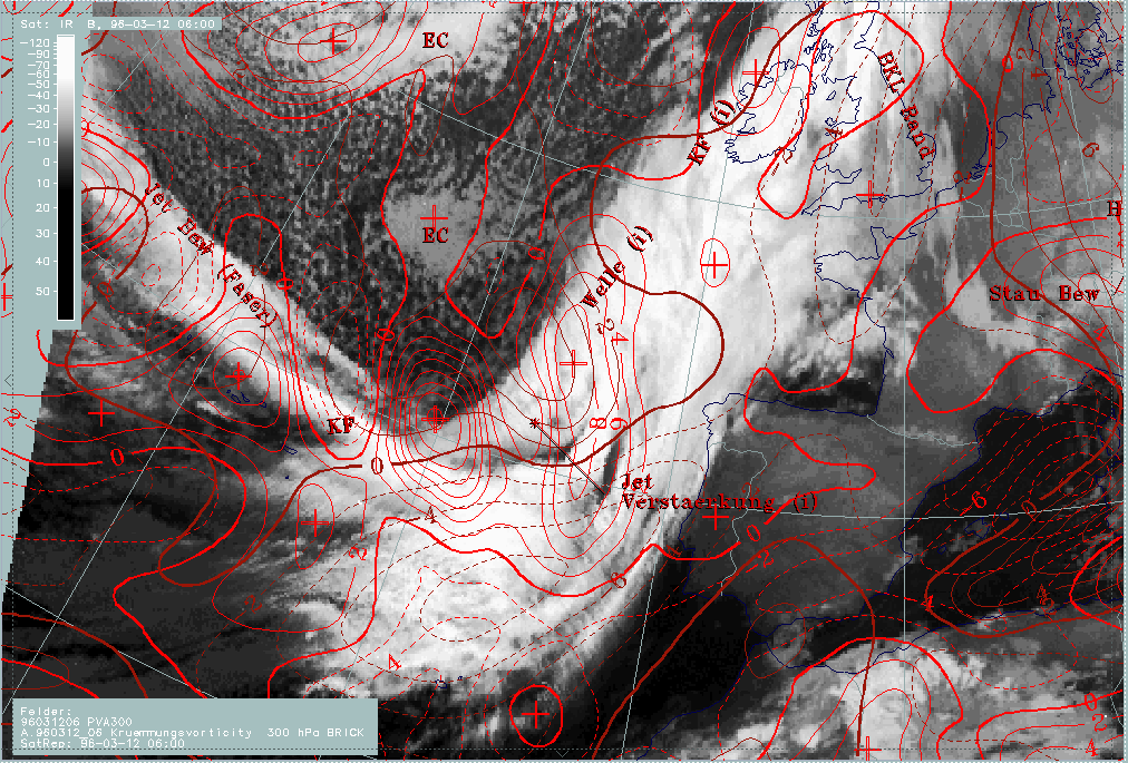
In the upper image isotachs and PVA maxima at 300 hPa are shown; for a more detailed discussion, have a look at the previous section (compare Diagnosis for 12 March 06.00 UTC ). Both lower images contain again in red colour the PVA maxima at 300 hPa, but also shear vorticity (left) and curvature vorticity (right) are included.
The different PVA maxima can be easily distinguished now. While the western maximum around 40N/20W is clearly related to the shear vorticity maximum (left image, blue isolines) and therefore indicates the left exit region, the northern maximum around 44N/15W is clearly related to the curvature maximum (right image, brown lines).The southern maximum of PVA around 40N/14W is related to a secondary shear vorticity maximum around 38N/14W. This is an indication of a south-eastward bend of the isotachs there.
After separating the different processes, the fact remains that the PVA maxima caused by shear are not consistent with the relevant area of typical cloud structure which can be diagnosed in the image. Therefore on concludes that the numerical model may not be quite correct here. Cloud structure in satellite images as a key parameter for the relevant conceptual model may help to get information about this. In both images, IR and WV, the cloud fibre crossing the cloud band of the Cold Front, which is an indication of the jet axis, can be continued as a straight line from W to E; compared to this the jet streak deviates in the area of the frontal cloud band in south-eastward directions causing the second, southern PVA maximum. This deviation could be an indication of a model error there. A shift of the isotachs from south-eastward to more eastward directions approximately along the cloud fibre would lead to a northward shift of the PVA maximum and a much better coincidence with the intensified frontal structure.
So at this point in time two decisions could be drawn from the additional parameters:
- A clear separation between shear and curvature effects which leads to a separation between the relevant cloud systems
- The assumption of a model error which shows a south-westward deviation of the jet streak over the area of the frontal cloud band leading to a shift of the PVA maxima; for this decision the form of the cloud fibre as a sign of the jet axis was used.
|
12 March 1996/06.00 UTC - Meteosat IR image; yellow: isotachs 500 hPa, black: positive vorticity advection (PVA) 500 hPa; SatRep
overlay: names of conceptual models
|
|

|
|
|
|
|
12 March 1996/06.00 UTC - Meteosat IR image; cyan: positive vorticity advection (PVA) 500 hPa, red: shear vorticity 500 hPa; SatRep
overlay: names of conceptual models
|
12 March 1996/06.00 UTC - Meteosat IR image; cyan: positive vorticity advection (PVA) 500 hPa, brown: curvature vorticity 500 hPa;
SatRep overlay: names of conceptual models
|
The situation at 500 hPa for the same point of time shows a different situation:
- The jet streak is in the western part of the cloud fibre to the south of the cloudiness; an explanation may be that the level is lower because cloudiness would be on the cyclonic side of the 500 hPa jet streak.
- In contrast to the jet streak at 300 hPa, the jet streak at the 500 hPa level turns to the north-east along the rear side of the Cold Front cloud band.
There are two main PVA maxima: one around 44N/19W and a southern one around 40N/21W. A comparison with shear vorticity (left panel) and curvature vorticity (right panel) clearly shows that curvature is the main cause for both PVA maxima. Shear is rather weak and contributes to both PVA maxima just to a minor degree.
|
12 March 1996/12.00 UTC - Meteosat VIS + IR image
|
|
|
This image shows a combination of the VIS and IR images which is useful for discriminating between low, thick and/or multilayered and high cloudiness which are false coloured in yellow, light yellow to white and blue, respectively.
At this point of time the cloud bulge of the wave is more pronounced than before and can be noticed from approximately 45N/14W, stretching northwards close to the west coast of Ireland.
Cloudiness in this area is only partly thick and/or multilayered whereas close to the western boundary of the Wave cloudiness only high cloudiness can be observed.
The region of the cloud fibre crossing the frontal cloud band and producing thereby a front intensification in the left exit region shows a very impressive difference between the high cloud fibre coloured in blue and the light yellow area immediately north of the fibre in the frontal cloud band (around 42N/13W). Concluding from the colour, this area can be regarded as a thick or at least multilayered area typical of the conceptual model "Jet Intensification". The cloud fibre shows at this time a slight cyclonic curvature and seems to cross the frontal cloud band immediately south of 40N turning southwards at the coast of Portugal.
As at 06.00 UTC also at this point of time the conceptual models "Wave" and "Jet Intensification" are close together and a separation of the two systems with the help of other key parameters is of interest.
|
12 March 1996/12.00 UTC - Meteosat IR image; yellow: isotachs 300 hPa, red: positive vorticity advection (PVA) 300 hPa
|
|
|
|
|
|
|
12 March 1996/12.00 UTC - Meteosat IR image; red: positive vorticity advection (PVA) 300 hPa, blue: shear vorticity 300 hPa
|
12 March 1996/12.00 UTC - Meteosat IR image; red: positive vorticity advection (PVA) 300 hPa, brown: curvature vorticity 300 hPa
|
The jet streak in the upper image (yellow lines) has a main maximum west of the cloud fibre, but an elongated lobe of the isotachs reaches into the area of the cloud band. As at 06.00 UTC, the jet streak represented by the isotachs deviates from the cloud fibre which is a key parameter for the location of the jet axis. It bends to southerly directions in the area of the frontal band. This was already the case at 06.00 UTC and was regarded as a possible model error there. Again, there are two main PVA maxima at 300 hPa:
- A northern one at the rear edge of the frontal cloud band between 48N/14W and 52N/12W which is related to the Wave area
- A southern one split up into two secondary maxima at approximately 41N/14W and 38N/10W which should belong to the area of the increased frontal cloudiness in the left exit region of the jet streak.
The interpretation of the two images containing shear and curvature vorticity leads at first to similar results as derived at 06.00 UTC. For the northern PVA maximum the driving parameter is curvature vorticity, for the southern one it is shear vorticity. Taking into account the wrong location of the eastern part of the jet streak by the model, and shifting the whole parameter configuration northward towards the cloud fibre seen in IR and WV, the PVA maxima would fit very well with the cloud area of the conceptual model "Jet Intensification".
But in addition to the main separation new features can also be noticed:
- A secondary weaker jet streak has developed along the rear boundary of the Wave bulge
- The maximum of curvature vorticity has widened and is shifted somewhat southward in relation to the crossing area of the cloud fibre and the intensified frontal cloudiness. Consequently an additional contribution of these two parameters to the PVA maxima cannot be excluded.
So for this time the following decisions can be summarized:
- The PVA maxima in the (or very close to the) relevant cloud areas of the frontal cloud band can be separated according to the main
processes:
- The northern one is mainly caused by a deepening trough and is related to the cloud bulge of the Wave;
- The southern two are mainly caused by a propagating jet streak and are related to the area of "Jet Intensification".
- As already stated for 06.00 UTC the location of the jet streak is not computed correctly, which leads to a southward shift of the PVA maxima compared to the cloud features.
- However, at this time new developments have taken place which may be regarded as first indications of a major change of the synoptic situation here: a secondary jet streak develops at the rearward edge of the Wave area, and the maximum of the upper level trough extends further southward to the area of Jet Intensification. The latter process may be indicated by the change to cyclonic curvature of the cloud fibre.
12 March 18.00 UTC
|
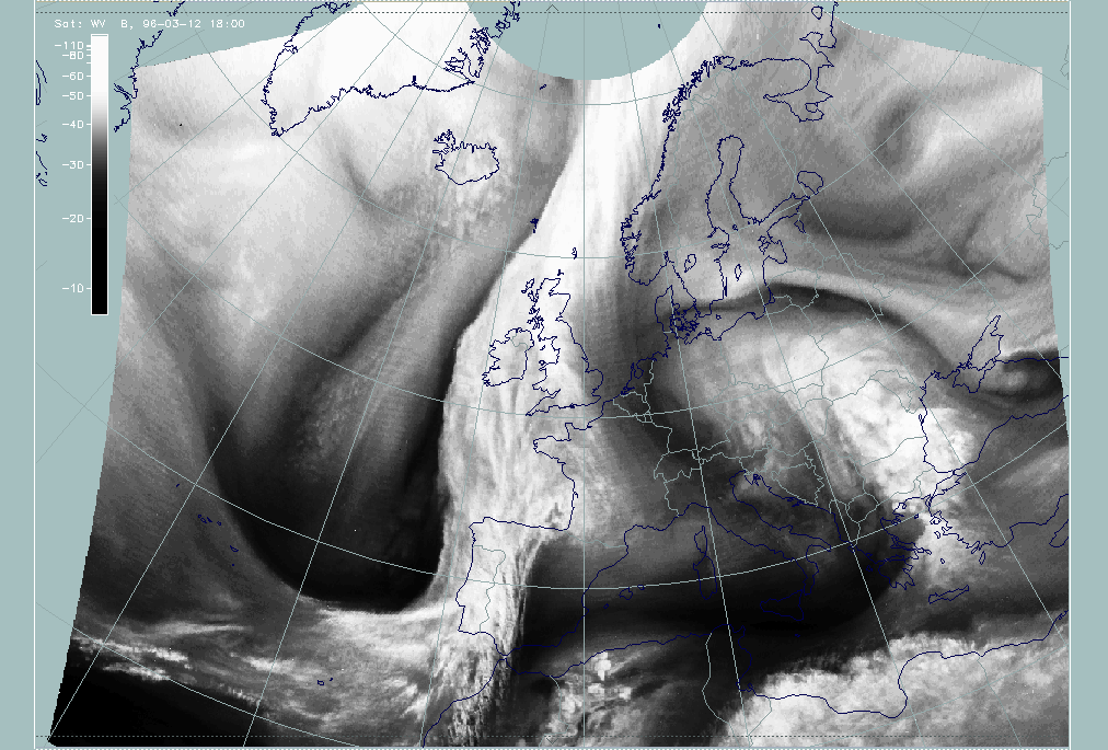
12 March 1996/18.00 UTC - Meteosat WV image
|
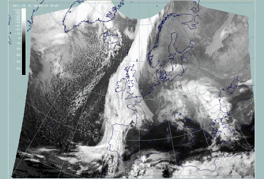
12 March 1996/18.00 UTC - Meteosat IR image
|
|
|
During the last six hours the western part of the cloud fibre has dissolved and only some fibres close to the frontal cloud band, crossing it west of south Portugal have remained. However, in the WV imagery the separation of wet air (grey) and a very dry area (black) is very distinct and can be regarded as a key parameter for the location of the jet axis.
|
12 March 1996/18.00 UTC - Meteosat IR image; yellow: isotachs 300 hPa, red: positive vorticity advection (PVA) 300 hPa
|
|
|
|
|
|
|
12 March 1996/18.00 UTC - Meteosat IR image; red: positive vorticity advection (PVA) 300 hPa, blue: shear vorticity 300 hPa
|
12 March 1996/18.00 UTC - Meteosat IR image; red: positive vorticity advection (PVA) 300 hPa, brown: curvature vorticity 300 hPa
|
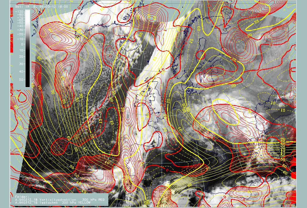
The orientation of the jet streak (yellow lines in the upper image), especially where it crosses the cloud band, is still not in conformity with the orientation of the cloud fibres as well as the Black Stripe in the WV image. Nevertheless, PVA maxima which have intensified during the last 6 hours fit much better now with the relevant cloud systems: the northern one in the area of the Wave bulge is around 50N/12W, the southern one immediately north of the cloud fibre in the frontal cloud band is around 40N/10W.
The images containing shear and curvature vorticity can give an explanation for the last statement. As already suggested for the situation at 12.00 UTC, a change has taken place in the synoptic situation. The main features are the increase of the upper level trough in the area of the "Jet Intensification" (brown lines, right image) and the increase of a secondary jet streak at the boundary of the Wave bulge (blue lines, left image).
Summarising this special investigation, several points could be shown:
- The separation of conceptual models which have PVA as a key parameter with the use of curvature and shear vorticity; in this case a "Wave area" could clearly be distinguished from a "Front Intensification area by Jet Crossing".
- The detection of model errors concerning the location of jet streaks and jet axis with the help of the WV image.
- The detection and evaluation of changes in the synoptic situation, for instance by the deepening of a trough. There are two effects of
this process on the cloudiness:
- The cloud fibres typically at the jet axis of a jet streak become a cyclonically curved shape and finally dissolve
- Cyclogenesis in the wave area does not develop but stagnates. Consequently, the cloud bulge of the Wave remains and develops more distinct cloud edges but no spiral structure appears.